12.4 Rendering Conventions for Geometric Shapes
The intent of this section is to describe the conventions for how CLIM should render a shape on a display device. These conventions and the accompanying examples are meant to describe a set of goals that a CLIM implementation should try to meet. However, compliant CLIM implementations may deviate from these goals if necessary (for example, if the rendering performance on a specific platform would be unacceptably slow if these goals were met exactly and implementors feel that users would be better served by speed than by accuracy). Note that we discuss only pixel-based display devices here, which are the most common, but by no means the only, sort of display device that can be supported by CLIM. [annotate]
When CLIM draws a geometric shape on some sort of display device, the idealized geometric shape must somehow be rendered on the display device. The geometric shapes are made up of a set of mathematical points, which have no size; the rendering of the shape is usually composed of pixels, which are roughly square. These pixels exist in "device coordinates", which are gotten by transforming the user-supplied coordinates by all of the user-supplied transformation, the medium transformation, and the transformation that maps from the sheet to the display device. (Note that if the last transformation is a pure translation that translates by an integer multiple of device units, then it has no effect on the rendering other than placement of the figure drawn on the display device.) [annotate]
Roughly speaking, a pixel is affected by drawing a shape only when it is inside the shape (we will define what we mean by "inside" in a moment). Since pixels are little squares and the abstract points have no size, for most shapes there will be many pixels that lie only partially inside the shape. Therefore, it is important to describe the conventions used by CLIM as to which pixels should be affected when drawing a shape, so that the proper interface to the per-platform rendering engine can be constructed. (It is worth noting that on devices that support color or grayscale, the rendering engine may attempt to draw a pixel that is partially inside the shape darker or lighter, depending on how much of it is inside the shape. This is called anti-aliasing.) The conventions used by CLIM is the same as the conventions used by X11: [annotate]
- A pixel is a addressed by its upper-left corner. [annotate]
- A pixel is considered to be inside a shape, and hence affected by the rendering of that shape, if the center of the pixel is inside the shape. If the center of the pixel lies exactly on the boundary of the shape, it is considered to be inside if the inside of the shape is immediately to the right (increasing x direction on the display device) of the center point of the pixel. If the center of the pixel lies exactly on a horizontal boundary, it is considered to be inside if the inside of the shape is immediately below (increasing y direction on the display device) the center point of the pixel. [annotate]
- An unfilled shape is drawn by taking the filled shape consisting of those points that are within 1/2 the line thickness from the outline curve (using a normal distance function, that is, the length of the line drawn at right angles to the tangent to the outline curve at the nearest point), and applying the second rule, above. [annotate]
It is important to note that these rules imply that the decision point used for insideness checking is offset from the point used for addressing the pixel by half a device unit in both the x and y directions. It is worth considering the motivations for these conventions. [annotate]
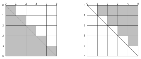
When two shapes share a common edge, it is important that only one of the shapes own any pixel. The two triangles in Figure 12.1 illustrate this. The pixels along the diagonal belong to the lower figure. When the decision point of the pixel (its center) lies to one side of the line or the other, there is no issue. When the boundary passes through a decision point, which side the inside of the figure is on is used to decide. These are the triangles that CLIM implementations should attempt to draw in this case. [annotate]
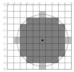
The reason for choosing the decision point half a pixel offset from the address point is to reduce the number of common figures (such as rectilinear lines and rectangles with integral coordinates) that invoke the boundary condition rule. This usually leads to more symmetrical results. For instance, in Figure 12.2, we see a circle drawn when the decision point is the same as the address point. The four lighter points are indeterminate: it is not clear whether they are inside or outside the shape. Since we want to have each boundary case determined according to which side has the figure on it, and since we must apply the same rule uniformly for all figures, we have no choice but to pick only two of the four points, leading to an undesirable lopsided figure. [annotate]
If we had instead chosen to take all four boundary points, we would have a nice symmetrical figure. However, since this figure is symmetrical about a whole pixel, it is one pixel wider than it ought to be. The problem with this can be seen clearly in Figure 12.3 if we attempt to draw a rectangle and circle overlaid with the following code: [annotate]
(defun draw-test (medium radius)
  (draw-circle* medium 0 0 radius :ink +foreground-ink+)
  (draw-rectangle* medium (- radius) (- radius) (+ radius) (+ radius)
                   :ink +flipping-ink+))
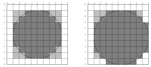
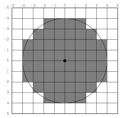
It is for this reason that we choose to have the decision point at the center of the pixel. This draws circles that look like the one in Figure 12.4. It is this shape that CLIM implementations should attempt to draw. [annotate]
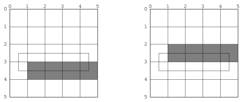
A consequence of these rendering conventions is that, when the start or end coordinate (minus 1/2 the line thickness, if the shape is a path) is not an integer, then rendering is not symmetric under reflection transformations. Thus to correctly and portably draw an outline of thickness 1 around a (rectilinear) rectangular area with integral coordinates, the outline path must have half-integral coordinates. Drawing rectilinear areas whose boundaries are not on pixel boundaries cannot be guaranteed to be portable. Another way to say the same thing is that the "control points" for a rectangular area are at the corners, while the control points for a rectilinear path are in the center of the path, not at the corners. Therefore, in order for a path and an area to abut seamlessly, the coordinates of the path must be offset from the coordinates of the area by half the path's thickness. [annotate]
12.4.1 Permissible Alternatives During Rendering
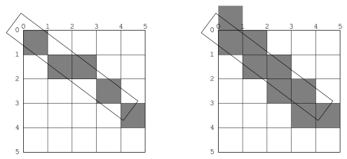
Some platforms may distinguish between lines of the minimum thinness from lines that are thicker than that. The two rasterizations depicted in Figure 12.5 are both perfectly reasonable rasterizations of tilted lines that are a single device unit wide. The right-hand line is drawn as a tilted rectangle, the left as the "thinnest visible" line. [annotate]
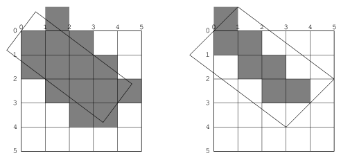
For thick lines, a platform may choose to draw the exact tilted fractional rectangle, or the coordinates of that rectangle might be rounded so that it is distorted into another polygonal shape. The latter case may be prove to be faster on some platforms. The two rasterizations depicted in Figure 12.6 are both reasonable. [annotate]
The decision about which side of the shape to take when a boundary line passes through the decision point is made arbitrarily, although we have chosen to be compatible with the X11 definition. This is not necessarily the most convenient decision. The main problem with this is illustrated by the case of a horizontal line (see Figure 12.7). Our definition chooses to draw the rectangular slice above the coordinates, since those pixels are the ones whose centers have the figure immediately above them. This definition makes it simpler to draw rectilinear borders around rectilinear areas. [annotate]